| 4A B Building Zhuao Industrial Park Gushu Xixiang Baoan District Shenzhen,China,518126 | info@newbridge.com.cn |
| 4A B Building Zhuao Industrial Park Gushu Xixiang Baoan District Shenzhen,China,518126 | info@newbridge.com.cn |
 |
| Place of Origin: | SHENZHEN,CHINA |
| Brand Name: | NEWBRIDGE |
| Certification: | FCC,CE |
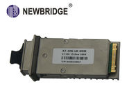
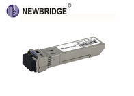
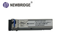
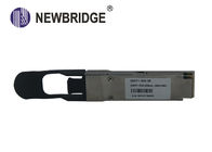
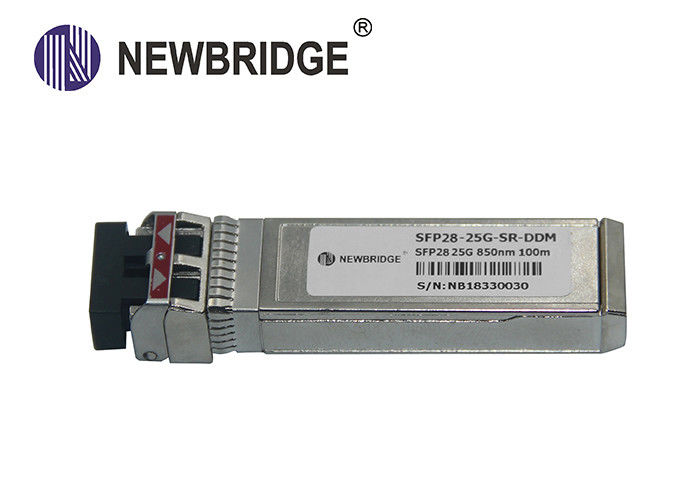
| Model Number: | SFP28 25G 850nm |
| Minimum Order Quantity: | 1PC |
|---|---|
| Price: | Negotiation |
| Packaging Details: | packing can be done by customer's requested, usually used in carton |
| Delivery Time: | According to the quantiy and stocking , 3-4 working days after payment |
| Payment Terms: | T/T , Western Union |
| Supply Ability: | According to the different products , the monthly output is different |
| Fiber: | Single Fiber | Device Type: | Optical SFP Module |
|---|---|---|---|
| Data Rate: | 25G | Operating Temperature: | 0°C To 70°C |
| Power Supply: | +3.3V | Low Power Consumptionor: | <1W |
Features:
² UP to 28.05Gb/s bit rates
² Hot-Pluggable
² Duplex LC connector
² 850nm VCSEL transmitter, PIN photo-detector
² Up to 100m on OM4 MMF, 70m on OM3 MMF
² 2-wire interface for management specifications compliant with SFF 8472 digital diagnostic monitoring interface for optical transceivers
² Cost effective SFP28 solution, enables higher port densities and greater bandwidth
² Power Supply :+3.3V
² Low Power consumption<1W
² Operating case temperature Range: 0~ 70°C
² RoHS compliant
Applications:
Description:
SH's SH001D is a very compact optical transceiver module converts 25Gbit/s serial PECL or CML electrical data into serial optical data compliant with the 25GBASE-SR standard. The SFP28 SR module electrical interface is compliant to SFI electrical specifications. The VCSEL transmitter and PIN receiver provide superior performance for Ethernet applications at up to 100m links on OM4 MMF.
The SFP+ Module compliant with SFF-8431, SFF-8432 and IEEE 802.3ae 25GBASE-LR. Digital diagnostics functions are available via a 2-wire serial interface, as specified in SFF-8472.
The fully SFP compliant form factor provides hot pluggability, easy optical port upgrades and low EMI emission.
l Absolute Maximum Ratings
| Parameter | Symbol | Min. | Typical | Max. | Unit |
| Storage Temperature | TS | -40 | +85 | °C | |
| Case Operating Temperature | TA | 0 | 70 | °C | |
| Maximum Supply Voltage | Vcc | 0 | 3.6 | V | |
| Relative Humidity | RH | 5 | 95 | % |
l Electrical Characteristics (TOP = 0 to 70 °C, VCC = 3.135 to 3.465 Volts)
| Parameter | Symbol | Min. | Typical | Max. | Unit | Note |
| Supply Voltage | Vcc | 3.135 | 3.465 | V | ||
| Supply Current | Icc | 300 | mA | |||
| Power Consumption | P | 1 | W | |||
| Data Rate | R | - | 25.8 | 28.05 | Gb/s | |
| Transmitter Section: | ||||||
| Input differential impedance | Rin | 100 | Ω | 1 | ||
| Tx Input Single Ended DC Voltage Tolerance (Ref VeeT) | V | -0.3 | 4 | V | ||
| Differential input voltage swing | Vin,pp | 180 | 700 | mV | 2 | |
| Transmit Disable Voltage | VD | 2 | Vcc | V | 3 | |
| Transmit Enable Voltage | VEN | Vee | Vee+0.8 | V | ||
| Receiver Section: | ||||||
| Single Ended Output Voltage Tolerance | V | -0.3 | 4 | V | ||
| Rx Output Diff Voltage | Vo | 300 | 900 | mV | ||
| Rx Output Rise and Fall Time | Tr/Tf | 9.5 | ps | 4 | ||
| LOS Fault | VLOS fault | 2 | VccHOST | V | 5 | |
| LOS Normal | VLOS norm | Vee | Vee+0.8 | V | 5 | |
Note:
1. Connected directly to TX data input pins. AC coupling from pins into laser driver IC.
2. Per SFF-8431 Rev 3.0
3. Into 100 ohms differential termination.
4. 20%~80%
5. LOS is an open collector output. Should be pulled up with 4.7k – 10kΩ on the host board. Normal operation is logic 0; loss of signal is logic 1. Maximum pull-up voltage is 5.5V.
l Optical Characteristics (TOP = 0 to 70°C, VCC = 3.135 to 3.465 Volts)
| Parameter | Symbol | Min. | Typical | Max. | Unit | Note |
| Transmitter Section: | ||||||
| Center Wavelength | λt | 840 | 850 | 860 | nm | |
| spectral width | △λ | 1 | nm | |||
| Average Optical Power | Pavg | -8.4 | +2.4 | dBm | 1 | |
| Optical Power OMA | Poma | -6.4 | -1.5 | 3 | dBm | |
| Laser Off Power | Poff | -30 | dBm | |||
| Extinction Ratio | ER | 2.0 | dB | |||
| Transmitter Dispersion Penalty | TDP | 3.8 | dB | TDB | ||
| Relative Intensity Noise | Rin | -128 | dB/Hz | 3 | ||
| Optical Return Loss Tolerance | 12 | dB | ||||
| Receiver Section: | ||||||
| Center Wavelength | λr | 840 | 850 | 860 | nm | |
| Receiver Sensitivity(OMA) | Sen | -10.0 | dBm | 4 | ||
| Stressed Sensitivity(OMA) | Sen2 | -5.2 | dBm | 4 | ||
| Los Assert | LOSA | -30 | - | dBm | ||
| Los Dessert | LOSD | -11 | dBm | |||
| Los Hysteresis | LOSH | 0.5 | 5 | dB | ||
| Overload | Sat | 3.5 | dBm | 5 | ||
| Receiver Reflectance | Rrx | -12 | dB | |||
Note:
1. Average power figures are informative only, per IEEE802.3ae.
2. TWDP figure requires the host board to be SFF-8431compliant. TWDP is calculated using the Matlab code provided in clause 68.6.6.2 of IEEE802.3ae.
3. 12dB reflection.
4. Conditions of stressed receiver tests per IEEE802.3ae. CSRS testing requires the host board to be SFF-8431 compliant.
5. Receiver overload specified in OMA and under the worst comprehensive stressed condition.
| Parameter | Symbol | Min. | Typical | Max. | Unit |
| TX_Disable Assert Time | t_off | 100 | us | ||
| TX_Disable Negate Time | t_on | 2 | ms | ||
| Time to Initialize Include Reset of TX_FAULT | t_int | 300 | ms | ||
| TX_FAULT from Fault to Assertion | t_fault | 1 | ms | ||
| TX_Disable Time to Start Reset | t_reset | 10 | us | ||
| Receiver Loss of Signal Assert Time | TA,RX_LOS | 100 | us | ||
| Receiver Loss of Signal Deassert Time | Td,RX_LOS | 100 | us | ||
| Rate-Select Chage Time | t_ratesel | 10 | us | ||
| Serial ID Clock Time | t_serial-clock | 100 | kHz |
| PIN # | Name | Function | Notes |
| 1 | VeeT | Module transmitter ground | 1 |
| 2 | Tx Fault | Module transmitter fault | 2 |
| 3 | Tx Disable | Transmitter Disable; Turns off transmitter laser output | 3 |
| 4 | SDL | 2 wire serial interface data input/output (SDA) | 4 |
| 5 | SCL | 2 wire serial interface clock input (SCL) | 4 |
| 6 | MOD-ABS | Module Absent, connect to VeeR or VeeT in the module | 2 |
| 7 | RS0 | Rate select0, optionally control SFP+ receiver. When high, input data rate >4.5Gb/ s; when low, input data rate <=4.5Gb/s | |
| 8 | LOS | Receiver Loss of Signal Indication | |
| 9 | RS1 | Rate select0, optionally control SFP+ transmitter. When high, input data rate >4.5Gb/s; when low, input data rate <=4.5Gb/s | |
| 10 | VeeR | Module receiver ground | 1 |
| 11 | VeeR | Module receiver ground | 1 |
| 12 | RD- | Receiver inverted data out put | |
| 13 | RD+ | Receiver non-inverted data out put | |
| 14 | VeeR | Module receiver ground | 1 |
| 15 | VccR | Module receiver 3.3V supply | |
| 16 | VccT | Module transmitter 3.3V supply | |
| 17 | VeeT | Module transmitter ground | 1 |
| 18 | TD+ | Transmitter non-inverted data out put | |
| 19 | TD- | Transmitter inverted data out put | |
| 20 | VeeT | Module transmitter ground | 1 |
Note:
The SFP modules implement the 2-wire serial communication protocol as defined in the SFP -8472. The serial ID information of the SFP modules and Digital Diagnostic Monitor parameters can be accessed through the I2C interface at address A0h and A2h.
The memory is mapped in Table 1.
Detailed ID information (A0h) is listed in Table 2.
And the DDM specification at address A2h.
For more details of the memory map and byte definitions, please refer to the SFF-8472, “Digital Diagnostic Monitoring Interface for Optical Transceivers”. The DDM parameters have been internally calibrated.
Table 1 - EEPROM Serial ID Memory Contents (A0h)
| Data Address |
Length (Byte) |
Name of Length |
Description and Contents |
| Base ID Fields | |||
| 0 | 1 | Identifier | Type of Serial transceiver (03h=SFP) |
| 1 | 1 | Reserved | Extended identifier of type serial transceiver (04h) |
| 2 | 1 | Connector | Code of optical connector type (07=LC) |
| 3-10 | 8 | Transceiver | 25G Base-LR |
| 11 | 1 | Encoding | 64B/66B |
| 12 | 1 | BR, Nominal | Nominal baud rate, unit of 100Mbps |
| 13-14 | 2 | Reserved | (0000h) |
| 15 | 1 | Length(9um) | Link length supported for 9/125um fiber, units of 100m |
| 16 | 1 | Length(50um) | Link length supported for 50/125um fiber, units of 10m |
| 17 | 1 | Length(62.5um) | Link length supported for 62.5/125um fiber, units of 10m |
| 18 | 1 | Length(Copper) | Link length supported for copper, units of meters |
| 19 | 1 | Reserved | |
| 20-35 | 16 | Vendor Name | SFP vendor name: SH |
| 36 | 1 | Reserved | |
| 37-39 | 3 | Vendor OUI | SFP transceiver vendor OUI ID |
| 40-55 | 16 | Vendor PN | Part Number: “SH001D” (ASCII) |
| 56-59 | 4 | Vendor rev | Revision level for part number |
| 60-62 | 3 | Reserved | |
| 63 | 1 | CCID | Least significant byte of sum of data in address 0-62 |
| Extended ID Fields | |||
| 64-65 | 2 | Option |
Indicates which optical SFP signals are implemented (001Ah = LOS, TX_FAULT, TX_DISABLE all supported) |
| 66 | 1 | BR, max | Upper bit rate margin, units of % |
| 67 | 1 | BR, min | Lower bit rate margin, units of % |
| 68-83 | 16 | Vendor SN | Serial number (ASCII) |
| 84-91 | 8 | Date code | SH’s Manufacturing date code |
| 92-94 | 3 | Reserved | |
| 95 | 1 | CCEX | Check code for the extended ID Fields (addresses 64 to 94) |
| Vendor Specific ID Fields | |||
| 96-127 | 32 | Readable | SH specific date, read only |
| 128-255 | 128 | Reserved | Reserved for SFF-8079 |
Digital Diagnostic Monitor Characteristics
| Data Address | Parameter | Accuracy | Unit |
| 96-97 | Transceiver Internal Temperature | ±3.0 | °C |
| 98-99 | VCC3 Internal Supply Voltage | ±3.0 | % |
| 100-101 | Laser Bias Current | ±10 | % |
| 102-103 | Tx Output Power | ±3.0 | dBm |
| 104-105 | Rx Input Power | ±3.0* | dBm |
SD HD SDI Converter , 20km 40km 60km Optional Mini Converter with single mode or single fiber
DC 12V Hdmi To Hd Sdi Converter SDI Signal Loop Out With 158×120×36mm Size
5V~24VDC Hdmi To Hd Sdi Converter 720p/1080p With 2 Channel SDI Signal Out
Plug And Play 60km HD SDI Converter , SD Auto Detection Optical Transceiver
RJ45 Port 100M Industrial Ethernet Switch/8 PoE port industrial network switch
High Efficiency 8 Port SFP PoE Ethernet Switch High Efficiency Easy Operating
Full Duplex Operation 24 Port PoE Ethernet Switch RJ45 Ports 100m 8.8G
LCD Display 16 Port Ethernet Switch 10 100Mbps 2G TP / SFP AC 240V Accurate
3D Video 4K HD HDMI Splitter 1 x 8 HDMI Splitter 1 In 8 Out
4K 1.4b 1 x 4 HDMI Splitter 1 In 4 Out Supporting 3D Video CE Certification
100Mbps RJ45 DC output 12V port poe splitter support IEEE 802.3at Poe Splitter HD HDMI Splitter